Device identification
- Device name: Shelly Plus 1PM
- Device model: SNSW-001P16EU
- Device SSID: ShellyPlus1PM-XXXXXX
Short description
Shelly Plus 1PM is a small form factor smart switch with power measurement, which allows remote control of electric appliances through a mobile phone, tablet, PC, or home automation system. It can work standalone in a local Wi-Fi network or it can also be operated through cloud home automation services.
Shelly Plus 1PM can be accessed, controlled and monitored remotely from any place where the user has internet connectivity, as long as the device is connected to a Wi-Fi router and the Internet.
It can be retrofitted into standard electrical wall boxes, behind power sockets and light switches or other places with limited space.
Shelly Plus 1PM has an embedded Web Interface that can be used to monitor and control the device, as well as adjust its settings.
Main applications
- Residential
- MDU (Multi Dwelling Units - apartments, condominiums, hotels, etc.)
- Light commercial (small office buildings, small retail/restaurant/gas station, etc.)
- Government/municipal
- University/college
Integrations
- Samsung SmartThings
- Alexa
Simplified internal schematics
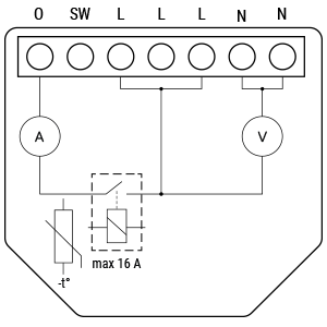
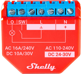
Device electrical interfaces
Inputs
- 1 switch/button input on screw terminal: SW
- 5 power supply inputs on screw terminals: 2 N (+) and 3 L (Ʇ)
Outputs
- 1 relay output with power measurement on screw terminal: O
Add-on interface
- Shelly proprietary serial interface
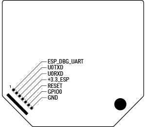
⚠ CAUTION! High voltage on the add-on interface when the device is powered!
Connectivity
- Wi-Fi
- Bluetooth
Safety features
- Overheating protection
- Overvoltage protection
- Overcurrent protection
- Overpower protection
Supported load types
- Resistive (incandescent bulbs, heating devices)
- Capacitive (capacitor banks, electronic equipment, motor start capacitors)
- Inductive with RC Snubber (LED light drivers, transformers, fans, refrigerators, air-conditioners)
User interface
Inputs
- One (Reset) button
- Press and hold for 5 seconds to enable device access point and Bluetooth connection.
- Press and hold for 10 seconds to factory reset the device.
Outputs
- LED (monocolor) indication
- AP enabled and Wi-Fi disabled: 1 second ON / 1 second OFF
- Wi-Fi enabled, but not connected to a Wi-Fi network: 1 second ON / 3 seconds OFF
- Connected to a Wi-Fi network: Constantly ON
- Cloud enabled, but not connected: 1 second ON / 5 seconds OFF
- Connected to Shelly Cloud: Constantly ON
- OTA (Over the Air Update): ½ sec ON / ½ sec OFF
- Button pressed and held for 5 seconds: ½ sec ON / ½ sec OFF
- Button pressed and held for 10 seconds: ¼ sec ON / ¼ sec OFF
The list above starts with the initial device status and the lowest priority. Every next state cancels the previous one.
Specifications
| Type | Value |
|---|---|
| Physical | |
| Size (HxWxD) | 37x42x16 ±0.5 mm / 1.46x1.65x0.63 ±0.02 in |
| Weight | 27 g / 0.95 oz |
| Mounting | Wall console |
| Screw terminals max torque | 0.4 Nm / 3.5 lbin |
| Conductor cross section | 0.5 to 1.5 mm² / 20 to 16 AWG |
| Conductor stripped length | 5 to 6 mm / 0.20 to 0.24 in |
| Shell material | Plastic |
| Color | Red |
| Environmental | |
| Ambient temperature | -20 °C to 40 °C / -5 °F to 105 °F |
| Humidity | 30 % to 70 % RH |
| Max. altitude | 2000 m / 6562 ft |
| Electrical | |
| Power supply | 110 - 240 VAC / 24 - 30 VDC |
| Power consumption | < 1.2 W |
| Output circuits ratings | |
| Max switching voltage AC | 240 V |
| Max switching voltage DC | 30 V |
| Max switching current AC | 16 A |
| Max switching current DC | 10 A |
| Sensors, meters | |
| Internal-temperature sensor | Yes |
| Voltmeter (AC) | Yes |
| Ammeter (AC) | Yes |
| Radio | |
| RF band | 2400 - 2495 MHz |
| Max. RF power | <20 dBm |
| Wi-Fi protocol | 802.11 b/g/n |
| Wi-Fi Range | Up to 30 m / 100 ft indoors and 50 m / 160 ft outdoors (Depends on local conditions) |
| Bluetooth Protocol | 4.2 |
| Bluetooth Range | Up to 10 m / 33 ft indoors and 30 m / 100 ft outdoors (Depends on local conditions) |
| MCU | |
| CPU | ESP32-U4WDH |
| Flash | 4 MB |
| Firmware capabilities | |
| Schedules | 20 |
| Webhooks (URL actions) | 20 with 5 URLs per hook |
| Scripting | Yes |
| MQTT | Yes |
| CoAP | No |
Basic wiring diagram
| 110–240 VAC power supply & Resistive load | 110–240 VAC power supply & Inductive load and RC snubber |
|---|---|
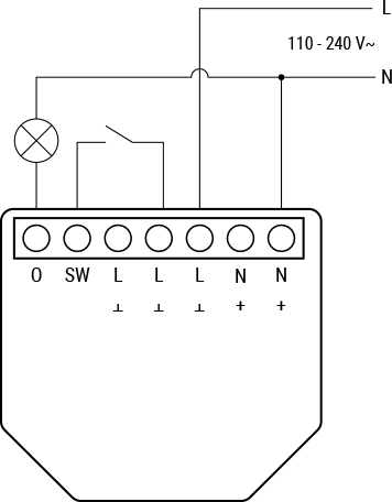 |  |
| 24–30 VDC power supply & Resistive load | 24–30 VDC power supply & Inductive load and RC snubber |
|---|---|
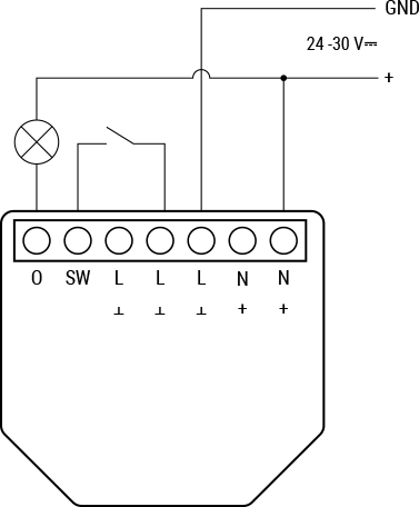 | 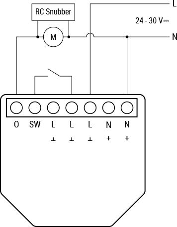 |
Legend
| Terminals | Description | Wires | Description |
|---|---|---|---|
| O | Load circuit output terminal | + | 24 - 30 VDC positive wire |
| SW | Switch (controlling O) input terminal | N | Neutral wire |
| L | Live (110–240 V) terminal | GND | 24 - 30 VDC ground wire |
| N | Neutral terminal | ||
| + | 24 - 30 VDC positive terminal | ||
| Ʇ | 24 - 30 VDC ground terminal |
Troubleshooting
Your device is overheating
- Make sure you are not using the L and N device terminals as bridges. Using them as bridges doubles the current through them, which leads to overheating. This is only safe with low currents so that the total current does not exceed 16 A.
- Ensure ambient temperature does not exceed 40 °C / 105 °F. If placed in a confined space, Shelly Plus 1PM may increase the ambient temperature above allowed limits. Ensure proper ventilation.
Web Interface guide
Read the Shelly Plus 1PM web interface guide
Components and APIs
Printed user guide
Shelly Plus 1PM multilingual user and safety guide
Compliance
- Shelly Plus 1PM multilingual EU declaration of conformity
- Shelly Plus 1PM UK PSTI ACT Statement of compliance
- Shelly Plus 1PM x2 UK PSTI ACT Statement of compliance
- Shelly Plus 1PM AU NZ Certificate for Suitability
Installation guides
There are no items with the selected labels at this time.