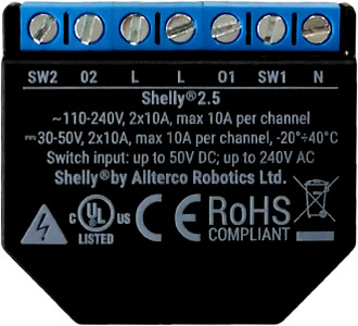
Shelly 2.5
Device Identification
- Device name: Shelly 2.5
- Device model: SHSW-25
- Device SSID: shellyswitch25-XXXXXX
Short Description
The Shelly 2.5 is a compact, two-channel smart switch with power measurement and cover control functionality. It enables remote control of electrical appliances via smartphone, tablet, PC, or home automation systems. The device operates standalone within a local Wi-Fi network or integrates with cloud-based home automation services.
Users can access, control, and monitor the Shelly 2.5 remotely from anywhere with internet connectivity, provided the device is connected to a Wi-Fi router and the Internet.
Designed for retrofit installation, it fits into standard electrical wall boxes, behind power outlets, light switches, or other space-constrained locations.
The device includes an embedded web interface for monitoring, control, and configuration of settings.
Main Applications
- Residential
- MDU (Multi Dwelling Units – apartments, condominiums, hotels, etc.)
- Light commercial (small offices, retail stores, restaurants, gas stations, etc.)
- Government / Municipal
- University / College
Integrations
- Google Assistant
- Samsung SmartThings
- Amazon Alexa
Simplified Internal Schematics
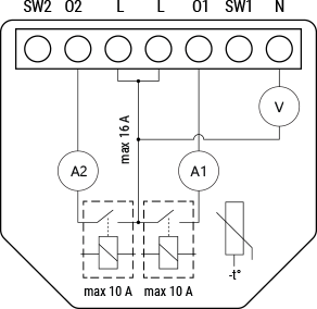
Device Electrical Interfaces
Inputs
- Two switch/button inputs on screw terminals
- Three power supply inputs on screw terminals: one Neutral (N), two Live (L)
Outputs
- Two relay outputs with built-in power measurement, accessible via screw terminals
Add-on Interface
- Shelly proprietary serial interface
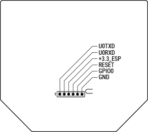
⚠ CAUTION: High voltage present on the add-on interface when the device is powered. Handle with care.
Connectivity
- Wi-Fi
- Bluetooth (for initial device pairing/inclusion only)
Safety Features
- Overheating protection
- Overpower protection
- Obstacle detection (in cover mode)
- Safety switch (in cover mode)
Supported Load Types
- Resistive (incandescent bulbs, heating devices)
- Capacitive (capacitor banks, electronic equipment, motor start capacitors)
- Inductive loads with RC snubber (LED drivers, transformers, fans, refrigerators, air conditioners)
User Interface
Inputs
- One (Reset) button
- Press and hold for 5 seconds to enable Access Point mode
- Press and hold for 10 seconds to perform a factory reset
Outputs
- Red LED indicator with the following status patterns:
| Status | LED Pattern |
|---|---|
| AP enabled, Wi-Fi disabled | 1 sec ON / 0.25 sec OFF |
| Wi-Fi enabled, not connected | 2 sec ON / 0.25 sec OFF |
| Connected to Wi-Fi network | Constantly ON |
| Cloud enabled, not connected | 1 sec ON / 5 sec OFF |
| Connected to Shelly Cloud | Constantly ON |
| OTA (Over-the-Air Update) in progress | 0.5 sec ON / 0.5 sec OFF |
| Button pressed and held for 5 seconds | 0.25 sec ON / 0.25 sec OFF |
| Button pressed and held for 10 seconds | 0.125 sec ON / 0.125 sec OFF |
Note: These states are prioritized in order. Higher-priority states override lower ones.
Specifications
| Category | Type | Value |
|---|---|---|
| Physical | Size (H×W×D) | 36 × 39 × 17 ±0.5 mm / 1.42 × 1.54 × 0.67 ±0.02 in |
| Weight | — | |
| Mounting | Wall console | |
| Screw terminals max torque | 0.4 Nm / 3.5 lbf·in | |
| Conductor cross section | 0.5 to 1.5 mm² / 20 to 16 AWG | |
| Conductor stripped length | 5 to 6 mm / 0.20 to 0.24 in | |
| Shell material | Plastic | |
| Color | Black | |
| Environmental | Ambient temperature | -20 °C to 40 °C / -5 °F to 105 °F |
| Humidity | 30% to 70% RH | |
| Max. altitude | 2000 m / 6562 ft | |
| Electrical | Power supply | 110–240 VAC / 30–50 VDC |
| Power consumption | <1 W | |
| Max switching voltage (AC) | 240 V | |
| Max switching voltage (DC) | 50 V | |
| Max switching current (AC) | 10 A per channel, 20 A total | |
| Max switching current (DC) | 10 A per channel, 20 A total | |
| Sensors & Meters | Internal temperature sensor | Yes |
| Wattmeter (AC) | Yes | |
| Radio | RF band | 2401–2495 MHz |
| Max RF power | <20 dBm | |
| Wi-Fi protocol | 802.11 b/g/n | |
| Wi-Fi range | Up to 30 m indoors / 50 m outdoors (varies by environment) | |
| MCU | CPU | ESP8266 |
| Flash memory | 2 MB | |
| Firmware Capabilities | Schedules | 20 |
| Webhooks (URL actions) | 12 hooks, up to 5 URLs per hook | |
| Scripting | No | |
| MQTT | Yes | |
| CoAP | Yes |
Basic Wiring Diagrams
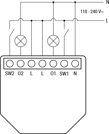
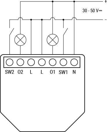
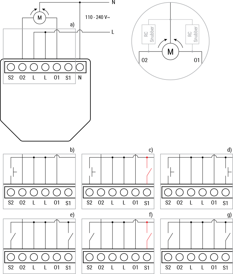
Legend
| Label | Description |
|---|---|
| Terminals | |
| N | Neutral terminal |
| L | Live (110–240 VAC) terminal |
| O1, O2 | Load circuit output terminals |
| + | 30–50 VDC positive wire |
| - | 30–50 VDC negative wire |
| SW1, SW2 | Switch input terminals |
| Wires | |
| N | Neutral wire |
| L | Live (110–240 VAC) wire |
Troubleshooting
(Content pending)
Web Interface Guide
Read the Shelly 2.5 Web Interface Guide
Components and APIs
Printed User Guide
Download printed user guide – English, Deutsch, Italiano, Español, Português, Français
Compliance
Shelly 2.5 Multilingual EU Declaration of Conformity.pdf
Installation Guides
(Content pending)
Projects
Home Automation: Roller Shutters, Lights, Scenes
A step-by-step guide to configuring and controlling roller shutters and ambient lighting using Shelly 2.5, integrated with Amazon Alexa. If you also own a Shelly Door/Window sensor, learn how to create automated scenes that adjust shutters or lights based on time of day and door status.
Genius Natural Beer Cooler With Wow Effect Controlled With Shelly Smart Device
Transform drain pipes into a natural underground beer cooler. An electrically driven pump brings chilled beer to the surface when needed. Control the system remotely via Siri or Alexa—just say: “Siri (or Alexa), bring beer.”
Reviews
We Smart
Shelly 2.5 Best Way to Install
Csongor Varga
Shelly 2.5 – Dual Channel Wi-Fi Relay with Roller Shutter Mode
The Hook Up
Does UL Listing Make Products Safer? Interview with Shelly About UL Certification of the Shelly 2.5